Pump Packing Application Data
B-4A Stuffing Box Packing
A typical packed stuffing box arrangement is shown in Fig. 5. It
consists of: A) Five rings of packing, B) A lantern ring used for the
injection of a lubricating and/or flushing liquid, and C) A gland to
hold the packing and maintain the desired compression for a proper
seal.

Fig. 5 Typical Stuffing Arrangement (description of parts)
The function of pump packing is to control
leakage and not to eliminate it completely. The packing must be
lubricated, and a flow from 40 to 60 drops per minute out of the
stuffing box must be maintained for proper lubrication.
The method of lubricating the packing
depends on the nature of the liquid being pumped as well as on the
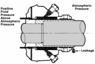
pressure in the stuffing box. When the pump stuffing box pressure is
above atmospheric pressure and the liquid is clean and nonabrasive, the
pumped liquid itself will lubricate the packing (Fig. 6).

Fig. 6 Typical Stuffing Arrangement when Stuffing Box Pressure is Above Atmospheric Pressure
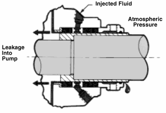
When the stuffing box pressure is below
atmospheric pressure, a lantern ring is employed and lubrication is
injected into the stuffing box (Fig. 7). A bypass line from the pump
discharge to the lantern ring connection is normally used providing the
pumped liquid is dean.

Fig. 7 Typical Stuffing Box Arrangement when Stuffing Box Pressure is Below Atmospheric Pressure
When pumping slurries or abrasive liquids,
it is necessary to inject a clean lubricating liquid from an external
source into the lantern ring (Fig. 8). A flow of from .2 to .5 gpm is
desirable and a valve and flowmeter should be used for accurate
control. The seal water pressure should be from 10 to 15 psi above the
stuffing box pressure, and anything above this will only add to packing
wear. The lantern ring Is normally located In the center of the
stuffing box. However, for extremely thick slurries like paper stock,
it is recommended that the lantern ring be located at the stuffing box
throat to prevent stock from contaminating the pump packing.

Fig. 8 Typical Stuffing Box Arrangement when Pumping Slurries
The gland shown in Figures 5 through 8 is
a quench type gland. Water, oil, or other fluids can be injected into
the gland to remove heat from the shaft, thus limiting heat transfer to
the bearing frame. This permits the operating temperature of the pump
to be higher than the limits of the bearing and lubricant design. The
same quench gland can be used to prevent the escape of a toxic or
volatile liquid into the air around the pump. This is called a
smothering gland, with an external liquid simply flushing away the
undesirable leakage to a sewer or waste receiver.
Today, however, stringent emission
standards limit use of packing to non-hazardous water based liquids.
This, plus a desire to reduce maintenance costs, has increased
preference for mechanical seals.
|

